Masonry Wall - Design
The masonry wall panel element allows you to easily model, analyze and design masonry walls for in plane
- The 2022, 2016 TMS 402 ASD and 2013, 2011, 2008, 2005, 2002 and 1999 Editions of ACI 530 ASD
- The 2022, 2016 TMS 402 Strength and 2013, 2011, 2008, 2005, 2002 and 1999 Editions of ACI 530 Strength
- The 1997 edition of the UBC for ASD and Strength
Here we will explain the calculation concepts and code references used in the program. For general wall panel information, see the Wall Panels topic. For information on masonry design rules, see the Masonry Wall - Design Rules (this is where you can define block thickness and self-weight). For masonry wall modeling procedures, see the Masonry Wall - Modeling topic. For masonry wall results interpretation, see the Masonry Wall Results topic.
- All code references in this topic refer to the TMS 402-22 specification unless noted otherwise.
- References will be made to RMEH and NCMA. For more information on these designations, see the Masonry Wall - Design Rules topic.
- Walls designed in RISA meet all of the requirements for Ordinary Masonry Shear Walls except for the Minimum Reinforcement requirements of TMS 402-22 Section 7.3.2.2.1. That provision should be checked by hand outside of RISA.
Shear Design - In Plane ASD
In Plane Shear Stress, fv
This stress is calculated from Equation 8-19:

where:
-
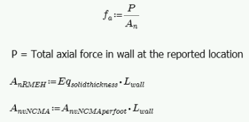
V = Total in plane shear in the wall region
-
Anv = net shear area
In RISA Anv is defined as follows:
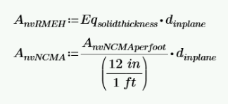
where:
-
dinplane = distance from compression face to centroid of boundary zone
-
Eqsolidthickness = value from RMEH textbook which represents the "average" thickness of wall considering block voids.
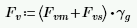
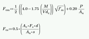
In Plane Shear Capacity, Fv
The program calculates the capacity, Fv, from Equation 8-20:

The program also checks to verify we do not exceed the Fv max value from Equations 8-21 and 8-22 (or interpolation between them) that is reported in the detail report.
Fvs is only required if fv > Fvm. If fv < Fvm, then the program will not add any shear reinforcement and Fvs = 0. If Fvs is required, then the program will back calculate a spacing, s, that will satisfy the steel shear capacity required. This shear spacing is reported in the detail report.
When shear reinforcement is required the program will also meet the d/2 or 48" spacing required by 8.3.5.2.1. If Fv max must be exceeded to pass the code check, the program will use Fv max as the capacity and state "Over Allowable" for the Shear Steel Spacing.
- The program does not do explicit seismic design, thus Equation 8-25 is not used.
- The M in the Fvm equation above is taken as the maximum moment in the region instead of the moment at the location where the shear is maximum.
Shear Design - Out of Plane ASD
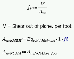
Out of Plane Shear Stress, fv
This stress is calculated from Equation 8-19:
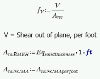
Out of Plane Shear Capacity, Fv
The program calculates the capacity, Fv, from Equation 8-20 shown above, except that only the Fvm term is considered. Currently the program does not allow the user to input additional shear reinforcement steel.
The program also checks to verify we do not exceed the Fv max value from Equations 8-21 and 8-22 (or interpolation between them) that is reported in the detail report.
Axial Design - ASD
In and Out of Plane Axial Stress, fa
The axial stress in a wall due to axial forces, fa, is calculated as:
This is applicable for all out of plane
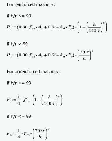
In and Out of Plane Axial Capacity, Fa
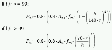
The calculation of Pa for reinforced masonry is Equation 8-16 or 8-17 and Fa for unreinforced masonry is per either Equation 8-11 or 8-12, depending on the h/r ratio. The equations are as follows:
where:
-
r is taken from the UBC-97 Table 21-H-1 (concrete masonry units) and Table 21-H-2 (clay masonry units).
-
h = effective height of wall region = K*hactual
Bending Design - ASD
In Plane Stresses fb and fs
These calculations are different depending on a cracked section or uncracked section. The wall is considered uncracked if fa (compression) > fb. The wall is considered cracked if fa (compression) < fb.
For uncracked masonry, the calculations are as follows:
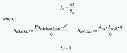
where:
-
d = Total length of wall
Because the masonry is uncracked, no stress can develop in the steel.
For cracked masonry, the program performs an iterative analysis to determine the section properties of the cracked wall.
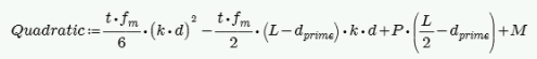
The maximum masonry stress (fm) is obtained by solving the moment equilibrium equation as a quadratic equation of kd. This equation comes from vertical equilibrium ( C - P - T = 0 ).
Here is a representative wall with axial force and moment:
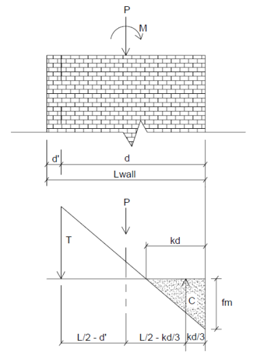
From this image we do a summation of moments about point T and come up with a quadratic equation in terms of kd.
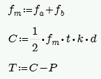
An assumption is made for fm = fa + fb, where fa = P/A and fb = M/S. From this C and T is determined. Once we calculate a value for T we can then define the boundary zone steel required. The final solution is determined through iteration. Each iteration of the steel area is based on the amount of steel needed to create a 0.005 ksi difference in the calculated bending stress (fb) and is carried out until the calculated value of required reinforcement is less than the reinforcement provided.
The final values are given in the detail report:
A good reference for this iterative procedure is Section 7.10.1 of Design of Reinforced Masonry Structures, copyright 2001 by Narendra Taly and published by McGraw-Hill.
From this analysis fm is calculated. This must then be broken down into fa and fb for the detail report. Because Section 8.3.4.2.2 states:
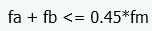
the proportion is simplified. RISA will simply take fa = P/An for fa and the remaining value from fm is used as fb.
From the tension force in the wall, T, the program calculates the required number of boundary zone bars and places them in the wall. The reported code check is then based on:
Out of Plane Stresses fb and fs
The masonry bending stresses are referenced in UBC Section 2107.2.15 and are as follows:
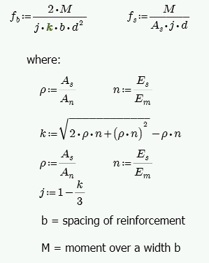
However, if you are using a partially grouted wall where the neutral axis passes through the webs of your masonry, then RISA will do a T-section analysis to define the section properties. We use a similar analysis as if you were doing a t-beam analysis for a concrete tee section. For more information on this, see "Design of Reinforced Masonry Structures" by Narendra Taly, copyright 2001, example 6.3, P6.61.
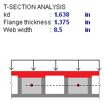
The area in red is shown as the compression block in the image above.
In and Out of Plane Masonry Bending Capacity, Fb
For unreinforced masonry, the Equation 8-13 is:

For reinforced masonry, Section 8.3.4.2.2 states:
Because of this provision, RISA defines:
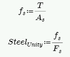
In and Out of Plane Steel Capacity, Fs
Section 8.3.3.1 defines the allowable steel stress, Fs.
In Plane Design - Strength
In Plane Axial Strength, Pn
This is calculated from Equations 9-13 and 9-14:
- Keep in mind that An is calculated differently for NCMA vs RMEH. See the Masonry Wall - Design Rules topic for more information.
- h = effective height of wall region = K*hactual
In Plane Moment Strength, Mn
The Mn value is based on the axial - moment interaction diagram for the wall based on strain compatibility at different levels of axial force. Once the interaction diagram is created the Mu is plotted and the code check is then calculated.
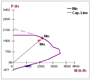
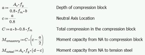
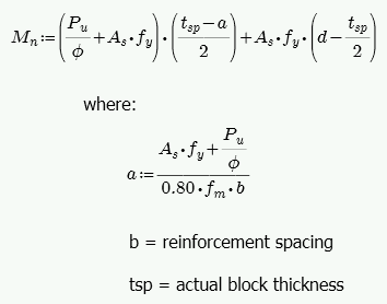
For a wall with no axial force, the Mn can be calculated from the equation:
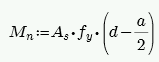
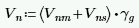
In Plane Shear Strength, Vn
The program calculates the capacity, Vn, from Equation 9-15:
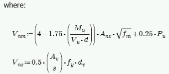
The program also checks to verify the Vn max value from Equations 9-16 and 9-17 (or interpolation between them) that is reported in the detail report is not exceeded.
Vns is only required if Vu > Phi*Vnm. If Vu < Phi*Vnm, then the program will not add any shear reinforcement and Vns = 0. If Vns is required, then the program will back calculate a spacing, s, that will both satisfy the steel shear capacity required and satisfy the maximum reinforcement spacing . This shear spacing is reported in the detail report.
If Vn max must be exceeded to pass the code check, the program will use Vn max as the capacity (so the wall fails in shear) and state "Over Allowable" for the Shear Steel Spacing.
Out of Plane Design - Strength
Out of Plane Axial Strength, Pn at max Mom
Here there are two different possible calculations.
If there is out-of-plane moment on the walls this is calculated from Section 9.3.4.4.2 as follows:
-
If h/t < 30, Pn at max Mom = 0.20*f'm*An
- If h/t > 30, Pn at max Mom = 0.05*f'm*An
If there is no out-of-plane moment this is calculated from Equations 9-13 and 9-14:
- t from the above equations is taken as the Block Nominal Thickness.
- h = effective height of wall region = K*hactual
Out of Plane Moment Strength, Mn
This calculation comes from the Commentary of Section 9.3.4.2 as follows:
The program is actually using an interaction diagram for out of plane bending as well. However, the code places a limit on axial force from Section 9.3.4.4.2. This limit essentially means that only the lower portion of the interaction diagram will be used. In this lower portion of the interaction diagram, the bending capacity changes in a linear fashion with respect to axial force.
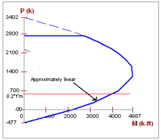
Thus, the equation above is nearly identical to the value that the program's interaction diagram will produce.
- In the case of high axial tension, it is possible that moment capacity will near zero.
- In partially grouted walls an effective width is calculated for b from Section 5.1.2
Out of Plane (Slender) Moment Demand, Mu
The out of plane demand moment, Mu, comes from the finite element analysis only. Equation 9-21 gives a formula for calculating the midheight moment due to out of plane loading, axial eccentric loading, and P-Little Delta effects. In RISA the first two portions can be captured by modeling the loads accordingly. Eccentric axial loading would need to be modeled with both a vertical load and a moment. The P-Delta analysis that RISA uses during the Finite Element solution does not account for P-Delta effects on plate elements or wall panels themselves. Instead the program captures P-Little Delta effects from the iterative procedure shown in the Moment and Deflection Amplification section below. This is very similar to that provided in the UBC and MSJC slender wall design provisions.
Out of Plane (Slender) Deflection, δs
Out of plane deflections are calculated based on the Wall's Finite Element Analysis using a modified thickness, tmod, for the wall plates. The modified thickness is calculated using the wall panel's out of plate cracked moment of inertia, Icr, which can be input in the Advanced tab of the Wall Panels spreadsheet.
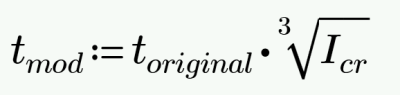
RISA-3D then uses Finite Element Analysis using the modified thickness of the plates to calculate the out of plane deflection of the wall.
Out of plane deflections are calculated very similarly to Section 9.3.4.4.2 equations 9-23 or 9-24. Note that because of P-Little Delta effects, moment and deflection calculations are iterative. RISA uses the iterative procedure as follows:
Moment and Deflection Amplification
- The initial moment diagram is calculated at 20 segments along the height of the wall using results taken directly from the FEM solution.
- The program then uses this moment and compares it to Mcr to see what proportion of moment is under Mcr and over Mcr. From this an equivalent moment of inertia (Iequiv) is calculated to approximate cracking, similar to Section 9.3.4.4.2.
- Using double integration and accounting for cracking the program calculates first order deflections.
- Using these first order deflections and the axial force in the wall the program adds in additional P-little delta moments.
- The program adds in the P-Delta moments based on these original elastic moments and deflections.
- New deflections and moments are calculated and compared to the results from the previous iteration. The program iterates the procedure until the results have converged within 0.5% of the previous iteration, or until it has iterated 100 times.
- This procedure is intended only to determine the localized P-Little Delta amplification of Moments and Deflections within the wall itself. This procedure does NOT amplify the shear forces, nor does it contribute to the "leaning wall" effect by pushing on the rest of the structure.
- Deflection calculations are only given for Service load combinations.
- The program calculates Iequiv based on a cracked section with a modified thickness that depends on the cracked factor Icr:MSJC equations that were specifically geared toward simply-supported and cantilever cases.
- Iequiv is taken from the maximum moment in a wall region and used to update the stiffness of the entire height of the wall.
- If the program iterates through this procedure 100 times it means that the wall is either too slender or too highly loaded. If this occurs then the message "Iterative P-Little Delta procedure did not converge. Wall is failing in bending." is reported.
Unreinforced Masonry Design - ASD
Out of Plane Bending and Axial Design - ASD
For out of plane design for axial and bending the program performs 3 checks: a compression check, a tension check, and a slenderness check.
Compression Check (per Equation 8-9)
where:
- fa and Fa are computed based on the equations for In and Out of Plane Axial Capacity, Fa
- fb = M/S. S = Sx value from NCMA TEK 141B (regardless of Wall Area Method designation).
- Fb = 1/3*f'm per Equation 8-13
Tension Check (per Section 8.2.4.2)
where:
-
Fbt = Allowable flexural tensile stress per Table 8.2.4.2
Slenderness Check (per Equation 8-10)
where:
-
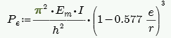
Per Equation 8-16.
-
I comes directly from NCMA TEK 141B for both Wall Area Methods, NCMA and RMEH.
-
e is always assumed equal to 0.
-
h = effective height of wall region = K*hactual
Out of Plane Shear Design - ASD
This stress is calculated from Equation 8-19:
The program calculates the capacity, Fv, from Equation 8-20 shown above, except that only the Fvm term is considered.
The program also checks to verify we do not exceed the Fv max value from Equations 8-21 and 8-22 (or interpolation between them) that is reported in the detail report.
In Plane Bending and Axial Design - ASD
For unreinforced masonry we use the same design provisions from reinforced masonry. Thus, we still use reinforcement for both the boundary zones and shear reinforcement (if needed). See the reinforced sections for more information on this design.
In Plane Shear Design - ASD
The in plane shear stress, fv, is calculated as follows:
The in-plane shear stress capacity, Fv, is calculated from Section 8.2.6.2. Because we do not know whether the wall is in running bond or not we omit options (c), (d), (e) and (f).
Unreinforced Masonry Design - Strength
Out of Plane Bending and Axial Design - Strength
For unreinforced masonry we perform the axial check per Section 9.3.4. For bending the program does not give results.
In Plane Bending, Axial, and Shear Design - Strength
For unreinforced masonry we use the same design provisions from reinforced masonry. Thus, we still use reinforcement for both the boundary zones and shear reinforcement (if needed). See the reinforced sections for more information on this design.
Masonry Lintel Design - ASD
Here we will talk about specific calculations regarding lintel design for allowable stress design.
Shear Stress, fv
This stress is calculated from Equation 8-19:

where:
- d = distance from extreme compression fiber in top of lintel to the centroid of reinforcement.
Shear Capacity, Fv
The program calculates the capacity, Fv, from Equation 8-20, which is shown in the previous In Plane Shear Capacity Fv section.
The program also checks to verify we do not exceed the Fv max value from Equations 8-21 and 8-22 (or interpolation between them) that is reported in the detail report.
Fvs is only required if fv > Fvm. If fv < Fvm, then the program will not add any shear reinforcement and Fvs = 0. If Fvs is required, then the program will back calculate a spacing, s, that will satisfy the steel shear capacity required. This shear spacing is reported in the detail report.
When shear reinforcement is required the program will also meet the d/2 or 48" spacing required by 8.3.5.2.1. If Fv max must be exceeded to pass the code check, the program will use Fv max as the capacity and state "Over Allowable" for the Shear Steel Spacing.
- The M in the Fvm equation above is taken as the maximum moment in the region instead of the moment at the location where the shear is maximum. This is generally a conservative assumption.
- The detail report shows a stirrup with two legs. However, the program only considers one leg in the Av calculation.
Bond Stress, u, and Bond Capacity U
The bond stress check is one that has been grandfathered in from the UBC-1997 specification section 2107.2.16 and is defined previously in the In Plane Bond Stress u section. Σo is the summation of the circumference of all vertical bars.
The bond stress capacity was defined previously in the Bond Stress Capacity U section.
Stresses fb and fs
The masonry bending stresses were defined previously in the Out of Plane Stresses fb and fs section.
Bending Capacity, Fm (Fb) and Steel Capacity, Fs
Section 8.3.4.2.2 states:
Section 8.3.3.1 defines the allowable steel stress, Fs.
Masonry Lintel Design - Strength
Here we will talk about specific calculations regarding lintel design for strength design.
Shear Strength, Vn
The program calculates the capacity, Vn, total from Equation 9-15, which was shown previously in the In Plane Shear Strength Vn section.
The program also checks to verify the Vn max value from Equations 9-16 and 9-17 (or interpolation between them) that is reported in the detail report is not exceeded.
Vn,steel is only required if Vu > Phi*Vn,masonry. If Vu < Phi*Vn,masonry, then the program will not add any shear reinforcement and Vn,steel = 0. If Vn,steel is required, then the program will back calculate a spacing, s, that will satisfy the steel shear capacity required. This shear spacing is reported in the detail report.
If Vn max must be exceeded to pass the code check, the program will use Vn max as the capacity (so the wall fails in shear) and state "Over Allowable" for the Shear Steel Spacing.
Moment Strength, Mn
Lintel design in RISA does not account for axial force, thus Mn is calculated simply from:
Here are the calculations of other values reported in the detail report: